
How to Assemble a Metal SeedSigner Plus
Assemble a metal SeedSigner Plus: prepare the display HAT and lid, install the camera and microSD extension, close the enclosure, and configure the larger display.

This guide walks through assembling the metal SeedSigner Plus: preparing the larger display, fitting the seven controls into the lid, connecting the camera and spring-loaded microSD extension, and completing the first boot.
Take your time around the camera connector and ribbon cables. Their retaining parts are small and can break if forced.
Watch the complete assembly
The video below demonstrates the electronics and general assembly order. It uses the PETG 3D-printed enclosure, not the metal case covered by this guide. The PETG enclosure’s Raspberry Pi snap-fit and microSD retaining shim do not apply to the metal case.
If the embedded player is blocked by your browser, watch the assembly video directly on YouTube.
Before you begin
Lay out every component and confirm that the display and camera ribbons are undamaged. Keep the flashed microSD card out of the extension while physically fitting the device.
Important: Do not sharply crease either ribbon cable. Use smooth bends, and hold PCBs by their edges rather than pressing on components.
Step 1 — Prepare the display HAT
- Place the display HAT on a clean, flat surface.
- Apply two strips of thin double-sided tape, each approximately 5–6 cm long, to the display mounting area.
- Connect the display ribbon to the HAT, making sure it is straight and fully seated.
- Remove the adhesive covers from the two tape strips.
- Carefully align the display with the PCB and press it down evenly.
- Hold it in place for a few seconds so the adhesive bonds.
Do not press hard on the centre of the LCD. Apply gentle pressure around its supported edges.
Step 2 — Prepare the lid
- Place the lid face-down on a clean surface.
- Place all seven button covers into the face-down lid.
- Remove the display’s screen protector.
- Align the display HAT with the lid and screen opening while keeping all button covers seated.
- Attach the standoffs and tighten them only until secure. Do not overtighten against the PCB.
- Carefully snap off the removable PCB edges. Support the board close to each breakaway edge and avoid flexing the populated section.
Step 3 — Connect and position the camera
- Locate the black camera-port retention bar on the Raspberry Pi Zero.
- Using a fingernail, ease each end of the lock outward by only about 1 mm. It does not detach from the connector.
- Slide the camera ribbon fully into the port with the shiny contacts facing the Pi’s contact side. A narrow line of the contacts may remain visible.
- Press both ends of the retention bar back into place to lock the ribbon.
- Apply the camera adhesive pad to the back of the camera module if it is not already fitted.
- Remove the adhesive cover.
- Gently fold the camera into its designated position on the back of the Pi, aligning it with the enclosure’s camera opening.
- Press it down for two to three seconds.
- Remove the protective film from the camera lens.
Use this close-up as the placement reference. The camera module sits against the rear of the Raspberry Pi PCB in the position shown:
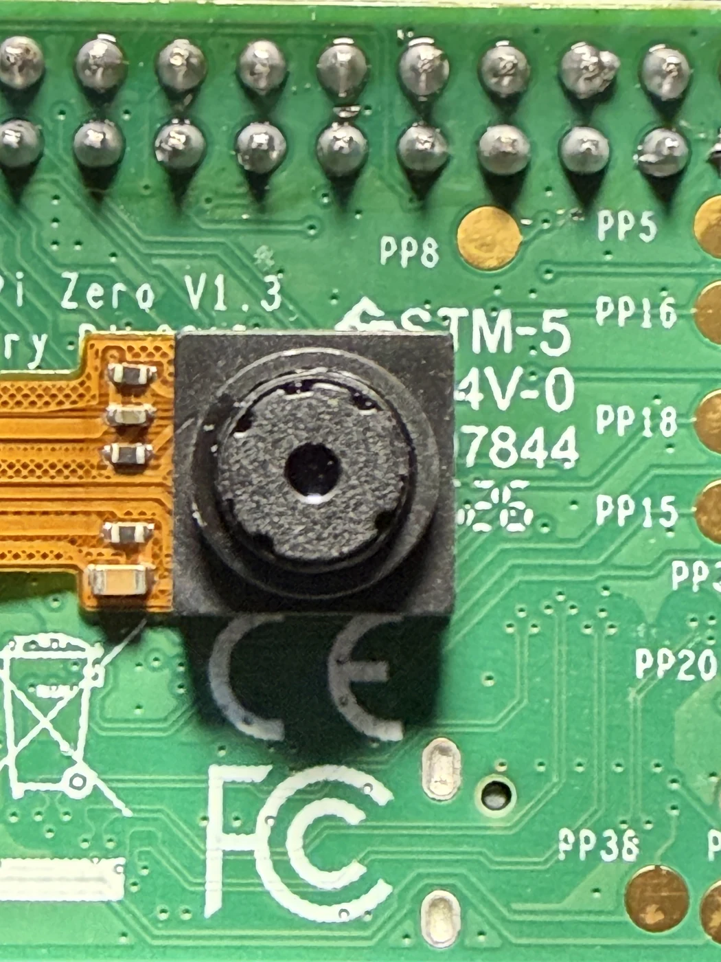
Camera position on the rear of the Raspberry Pi Zero PCB (reference image IMG_5673).
Do not pull the camera lock out: it moves only slightly. Pulling harder can break the connector off the Raspberry Pi.
Step 4 — Connect the microSD extension
- Hold both the Raspberry Pi and the male end of the microSD extension securely.
- Insert the extension into the Pi’s microSD slot until it reaches its stop. Through the slot openings, confirm that it is fully inserted.
- Place a small piece of thin adhesive inside the mouth of the enclosure’s microSD-card slot, where it will secure the extension socket without obstructing the card path or spring mechanism.
- Leave the microSD card out while you fit the extension into the enclosure.
Use only enough adhesive to prevent the socket from shifting. Adhesive must not enter the socket or cover the card opening.
Step 5 — Bench-test the electronics
Testing now is much easier than removing the electronics from the enclosure later.
- Align the Pi’s GPIO header with the female header on the display HAT and press them together evenly.
- Insert the verified SeedSigner microSD card into the extension.
- Connect USB-C power to the display HAT.
- Allow roughly 15–20 seconds for SeedSigner to boot.
- Open Settings → Advanced → I/O Test and test left, right, up, down, centre and the three side buttons.
- Take a test photo to confirm the camera is working.
- Disconnect power and remove the microSD card.
- Gently separate the HAT and Pi by alternating between the two ends of the GPIO header.
Do not continue until the display, every button, the microSD extension and the camera all pass the test.
Step 6 — Position the Raspberry Pi in the metal base
- Check that the camera is still centred over the base’s camera opening.
- Lower the Pi into the base at an angle, guiding its two micro-USB ports and mini-HDMI port into their enclosure openings.
- Lower the opposite edge gently until the board sits level in its designated position.
- Inspect all port openings and recheck the camera alignment.
Metal-case difference: Do not try to snap the Raspberry Pi into the base. The snap-fit retention bumps shown in the video belong to the PETG 3D-printed enclosure and are not present in the metal case.
Step 7 — Secure the microSD extension in the metal case
- Curve the extension ribbon gently so the spring-loaded socket sits at roughly 90 degrees to the Pi. Do not make a sharp crease.
- Seat the socket squarely in the base’s microSD opening and onto the adhesive placed earlier.
- Press the socket gently onto the adhesive so it stays aligned with the mouth of the slot.
- Insert and eject the microSD card several times to confirm the spring-loaded mechanism works freely.
- If the card catches, stop and realign the socket. Do not pull the card out with force.
- Remove the card before continuing.
Metal-case difference: The metal enclosure does not use the microSD retaining shim shown in the PETG assembly video.
Step 8 — Install the display HAT
- Guide the extension ribbon down so it rests near the base of the GPIO pins and will not be trapped.
- Align the display HAT’s female GPIO header with the Pi’s pins.
- Lower the HAT into the base, checking that it sits on the perimeter and internal supports.
- Press evenly above the GPIO header until it is fully seated.
- Inspect all sides. The HAT should rest level with no cable pinched underneath it.
Step 9 — Fit the lid
- Confirm that all seven button covers remain seated in the face-down lid.
- Lower the lid over the display HAT while keeping the buttons captured in their openings.
- Check that the screen fits inside the four locating corners without resistance.
- Press around the lid evenly until it locks into the base.
- Test every button mechanically. Each should move freely and return normally.
If the lid will not close easily, stop and check the button orientation, screen alignment and extension ribbon. Do not force the metal enclosure together.
Step 10 — First boot and SeedSigner Plus settings
- Insert the flashed microSD card into the external spring-loaded slot.
- Connect USB-C power.
- Confirm that the activity light flashes and wait for the interface to appear.
- Go to Settings → Persistent Settings and enable persistent settings so the following choices survive a reboot.
- Go to Settings → Advanced → Hardware → Display Type.
- Select ST7789 320×240. The default 240×240 option will show only a square section of the interface on the larger screen.
- Set Camera Rotation to 0° for this enclosure and camera orientation.
- Run the I/O test once more and take a final test photo.
- Reboot and confirm the display and camera settings were retained.
Your metal SeedSigner Plus is now assembled and ready for normal SeedSigner setup.
Troubleshooting
Only a square portion of the interface is visible
Select ST7789 320×240 under Settings → Advanced → Hardware → Display Type. Enable persistent settings first.
The camera image is upside down
Set Camera Rotation to 0° for this enclosure.
SeedSigner does not detect the microSD card
Power off, then check that the extension’s male end is completely inserted into the Pi. Confirm that the external socket is square in the enclosure and that no adhesive obstructs its card path.
A button is held down or does not click
Open the enclosure and place all seven button covers back into the face-down lid before aligning the display HAT again.
The camera is not detected
Power off before touching the connector. Reopen the camera lock by about 1 mm, reseat the ribbon straight and fully, then close both ends of the lock.
What’s next
- Download and verify SeedSigner software only from the official SeedSigner repository.
- Learn the signing workflow in our first hardware wallet setup guide.
- Practise with a test seed and small-value wallet before relying on the device for significant funds.
Frequently Asked Questions
Which SeedSigner image does the SeedSigner Plus use?
The standard SeedSigner Plus uses a Raspberry Pi Zero v1.3, so use the pi0 image from the official SeedSigner release. Verify its signature and SHA-256 hash before flashing.
Which display type should I select?
Enable persistent settings, then choose ST7789 320×240 under Settings → Advanced → Hardware → Display Type.
What camera rotation should I use?
For this metal SeedSigner Plus enclosure and camera position, set Camera Rotation to 0 degrees.
Why does the microSD card feel tight?
Check that the extension socket is square in the metal case opening and that the adhesive is not obstructing the card path or spring mechanism. Never force the card.